


The production of a motor is a multi-step process. Here, I will describe the production of the motor's rotor. Rotor production involves nine steps.
1. Rotor shaft pressing
The first step is to press the rotor onto the shaft, aiming to securely fix the rotor stcak to the shaft. Applying the principle of interference fit, the rotor stack and shaft are successfully connected under the operation of the machine.

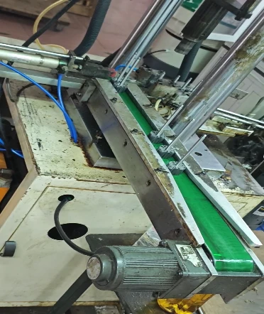
2. Press the white end plate
The second step is to press the end plates onto the connected rotor stack and shaft. This step provides stability to the rotor stack, preventing the lamination from loosening, shifting, or flying apart due to expansion caused by the enormous centrifugal force generated when the rotor rotates at high speed.

3. Insert the slot paper
The third step is to insert slot insulation paper into the rotor. A layer of insulating paper is inserted into the slots of the rotor stack. This prevents direct contact between the wires and the rotor stack, avoiding short circuits.


4. Press the commutator
The fourth step is to press-fit the commutator. The commutator is firmly press-fitted onto the motor rotor shaft. When the motor rotates at high speed, the commutator is subjected to enormous centrifugal force, and the tight press-fit can resist such huge centrifugal force. Meanwhile, it ensures good heat conduction, efficiently transferring the heat generated by the commutator to the rotor stack and shaft, which is then dissipated through the bearings.

5. Rotor winding
The fifth step is rotor winding. Copper wires are embedded into the iron core according to a specific winding pattern and number of turns. The coils that generate the electromagnetic field are the core working components of the motor.


6. Slot puncher
The sixth step is slot punching. The purpose is to assist the wires in being smoothly, quickly, and neatly embedded into the core slots where the slot paper has already been inserted, while ensuring that the slot paper is not damaged or displaced.


7. Spot welding
The wires of the rotor coil are firmly welded to the commutator. This ensures efficient and stable current conduction and enables it to withstand the vibrations and centrifugal forces generated by the high-speed rotation of the rotor. Insufficient welding or poor contact will cause an increase in resistance at the connection point, abnormal heating, and even the generation of sparks or arcs. This will ablate the welding points, damage the coil insulation or commutator, and ultimately result in the motor being weak, operating unstably, or even completely burning out.

8. Vacuum Impregnation
By impregnating with insulating paint and curing through high-temperature baking, a strong and dense insulating protective layer is formed between the rotor coil, rotor stack, and on their surfaces. Impregnation serves to bond the coil firmly, enhance insulation, prevent moisture, and improve heat dissipation. If impregnation is not performed, the insulation strength of the coil will be insufficient and its structure will be loose. During high-speed rotation, the coil is prone to displacement and friction, leading to insulation damage, and it is highly likely to cause inter-turn short circuits or ground short circuits.

9. Turning
Use a precision lathe to cut and machine the outer circular surface of the commutator to obtain a smooth and flat surface. This is the basis for ensuring good and stable contact between the carbon brush and the commutator. If the commutator is not turned, an uneven surface, eccentricity or grooves will cause the carbon brush to jump, poor contact, and intense sparks.


before turning after turning


