


Stepper motor through the PLC for positioning control program
Positioning plan
To ensure the positioning accuracy of the system, the pulse equivalent, that is, the interval between the stepping motor and the step angle should not be too large, and the stepping motor should be slow to prevent the occurrence of out-of-step or overshoot. But the combination of these two elements brings up an outstanding problem: the positioning time is too long, affecting the efficiency of the execution organization.
Therefore, in order to achieve a high positioning speed, together with the positioning accuracy, the entire positioning process can be divided into two phases; the coarse positioning phase and the fine positioning phase
Coarse positioning stage
Use a larger pulse equivalent, such as 0.1mm / step or 1mm / step, or even higher.
Fine positioning stage
In order to ensure the positioning accuracy, use a smaller pulse equivalent, such as 0.01mm / step. Although the pulse equivalent is small, since the fine positioning stroke is short (can be set to about one-fifth of the full stroke), it does not affect the positioning speed. In order to accomplish this, the mechanical aspects can be accomplished by using different shifting configurations.
Industrial machine tool control plays an important role in industrial automation control, and positioning drilling is a common step. Set the tool or workbench to move from point A to point C, known as AC=200mm, divide AC into two sections AB and BC, AB=196mm, BC=4mm, AB section is the coarse positioning stroke, select 0.1mm/step The pulse equivalent is quickly moved according to the linear lifting frequency law, and the BC segment is the fine positioning stroke. The pulse equivalent of 0.01 mm/step is selected, and the accurate positioning is performed by the low-frequency constant-speed motion of point B. Together with the fine positioning after the rough positioning is completed, the PLC automatically completes the replacement of the shifting organization.
Overview of the positioning program design content
PLC pulse output command
More advanced PLCs now not only have the fundamental logic instructions that satisfy the order control requirements, but also provide a wealth of utility instructions. The PLUS command of the SiemensS7-200 series PLC outputs PTO or PWM high-speed pulses at Q0.0 and Q0.1, and the maximum output frequency is 20KHz. The pulse train (PTO) supplies a square wave output (50% duty cycle), user control period and number of pulses. Pulse width modulatable (PWM) ketone energy can be supplied to successive, variable duty cycle outputs, user control cycles and pulse widths.
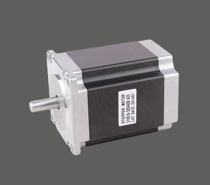
In this paper, the multi-stage pipeline operation method of PTO is used to complete the coarse positioning, and the single-stage pipeline method of PTO completes the fine positioning.
In the above, for example, it is assumed that the starting and finishing frequency of the motor is 2 kHz, and the maximum pulse frequency is 10 kHz. In the coarse positioning process, the upsizing is accelerated with 200 pulses, and the downsizing is performed with 400 pulses. When using the PLC PTO multi-stage pipeline pulse output, use the following formula to calculate the pulse increment value in the lifting frequency process.
If you want to buy a vacuum cleaner motor, please pay attention to Low Noise Dust Collector Motor.


