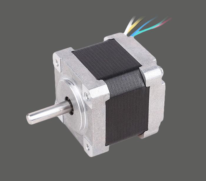
Stepper motor control system block diagram and design principle
1 system design principle
The stepper motor control system is mainly composed of four modules, such as single chip microcomputer, keyboard LED, drive/amplification and PC upper computer. The PC module is the software control part. In order to protect the hardware circuit of the single-chip control system, an overcurrent protection circuit is added between the single-chip microcomputer and the stepping motor. Figure 1 is a block diagram of the stepper motor control system.
2 system hardware circuit design
2.1 single chip module
The MCU module is mainly composed of MSP430FG4618 MCU and peripheral filtering, power management and crystal oscillator.
The 8KBRAM and 116KBFlash inside the MSP430FG4618 MCU meet the storage requirements of the control system. The P1 and P2 ports change the working state of the stepper motor according to the state of the button during the working process of the stepper motor. The USART module implements the MCU and PC. The communication between the upper computer realizes the control of the stepping motor by the PC.
2.2 keyboard / LED module
In order to realize man-machine dialogue, the system design expands the 3x4 button matrix keyboard and four 8-segment LED digital tubes, which can be directly operated directly by the control system.
After the system is powered on, the start and stop of the stepping motor, the number of steps and the steering are input through the keyboard, and the speed and steering of the stepping motor are dynamically displayed by the LED tube. The input of the keyboard and the output of the LED tube are controlled by 8279, which reduces the workload of the microcontroller.
The 8279 programming works in the keyboard scan input mode, and has a debounce function when reading the keyboard to avoid false triggering. Figure 3 is a block diagram of the design structure of the keyboard LED module.
2.3 drive / amplification module
The control system uses a pulse splitter (also known as a logic converter) PMM8713 for stepper motor control. The device is a CMOS integrated circuit with phase output drive capability (source current or sink power) of 20mA. It is suitable for controlling three-phase or four-phase. Stepper motor, can choose the following 6 kinds of excitation modes: three-phase stepping electric advance: 1 phase, 2 phase, 1-2 phase; four phase stepping electric advance: 1 phase, 2 phase, 1-2 phase. The input mode can be selected from single clock (plus direction signal) and dual clock (forward or reverse clock), with functions such as forward and reverse control, initial reset, origin monitoring, excitation mode monitoring and input pulse monitoring.
3 system software design
3.1 microcontroller program
The timer is generated by the timer TIMER_A(TA) interrupt of the single-chip microcomputer, and the accurate counting of the number of steps and the number of turns of the stepping motor is realized in the response interrupt program, and the speed control is realized by PWM; the interrupt of the P1.0 port is used to turn off the TA interrupt. The program is pushed onto the stack to stop the motor; P1.1 interrupt turns on the TA interrupt, the stack pushes into the program counter (PC), turns on the motor; P3.1 port outputs the high level controlled by the PMM8713 U/D port. ; P3.0 ~ P3.7 port connected to 8279 8 data interface, when the MCU scans to the matrix keyboard with key press, use the P2 port interrupt to set TA, control start and stop, speed and steering, etc., while MCU feedback Give 8279 control LED tube display speed and steering. The program flow is shown in Figure 5.
3.2PC host computer module
The PC host computer module realizes the control of the stepping motor by the PC. The USART module of the MSP430 single-chip microcomputer is used to realize communication with the PC host computer, and the PC sends a control command to the single-chip microcomputer through the serial port to realize motor control.
The control command received by the MCU is temporarily stored in RXBUFFER, and then compared with the entry address of the interrupt program stored in the on-chip flash, and the same interrupt is entered to realize the control of the stepping motor. When operating this module, you need to turn on the 8MHz crystal to set the baud rate for the USART module (set the baud rate to 9600).
The control software is written by VB6.0 and uses the MSComm control to implement serial communication functions. Its control software interface is shown in Figure 6.
4 system testing
In order to verify the actual working condition of the control system, the maximum static torque output by the stepping motor is measured by the energy conversion method given the output current of the PMM2101. The static characteristic curve of the relationship between the maximum static torque and the current of the stepping motor is measured by selecting the output current interval of 0.2A. As shown in Fig. 7, the design of the control system is reasonable.